By David Robert January 14, 2024
Dumping firmware of in-module ESP32 flash
In my previous article, I wrote about secure boot. In this article, I want to demonstrate one way to dump the ESP32 in-module flash memory, which works, even if different security features are set by burning e-fuses on the chip (JTAG, UART, DFU disabled). This article aims to illustrate the need for secure boot and flash encryption. Dumping, and modifying the firmware is important for testing the mitigations for the threats identified in your device’s threat model. That is an important task to do in any device testing.
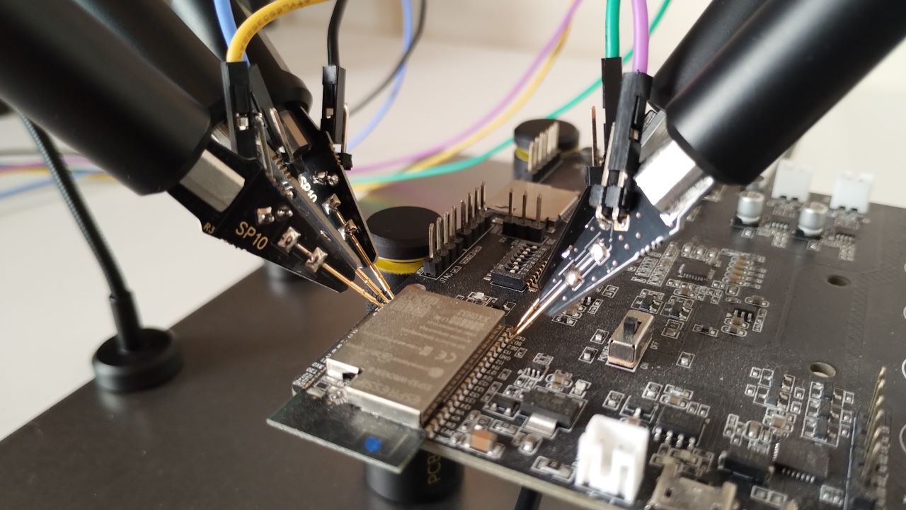
Firmware dumping
There are several ways to dump the firmware on embedded systems. The most common are JTAG/SWD, UART, USB-to-UART bridge, DFU, and by connecting directly to the flash chip.
With the ESP32 series, you can disable most of these methods by burning e-fuses, leaving the tester with only the last option. (I will cover in a future article the use of fault injection.)
The ESP32 uses NOR flash SPI memory to store the firmware. The location of this flash memory can vary among different designs. A flash chip can be found directly on the PCB, often as a SOIC-8 package. A flash chip could be on the PCB inside of an ESP32 module. Finally, the flash memory can be directly integrated into the ESP32 SoC package.
Test with the ESP32WROVER
Looking at the peripheral reference schematic provided by Espressif, you’ll notice that pins 17 to 20 are not connected:

Espressif indicates that these pins should not be used, because they are connected the the internal SPI flash:

Now that’s interesting. This could be an easy task to access the internal flash directly via the SPI protocol.
Many embedded security engineers like to use specific interfaces to communicate on ports like UART or SPI. These interfaces are generally connected to USB to a computer running firmware upload/download software. Examples of such interfaces are BusPirate, Zipper Zero, Hydrabus, CH341A, 232H programmers, etc.
In my case, having access to embedded Linux systems, I want to leverage Linux, running on SoCs, which have already all these hardware peripherals (SPI, UART, etc.). The flexibility of driving a SPI bus directly from Linux user land, for instance directly in Python, outperforms (for my needs) external USB interfaces. In this case, I am simply connecting the ESP32 module to the SPI pins of a Raspberry Pi, and voila! For $15 you can buy a RPI W 2 with 1GHz and 512MB of SDRAM. This is a perfect hardware hacking tool.
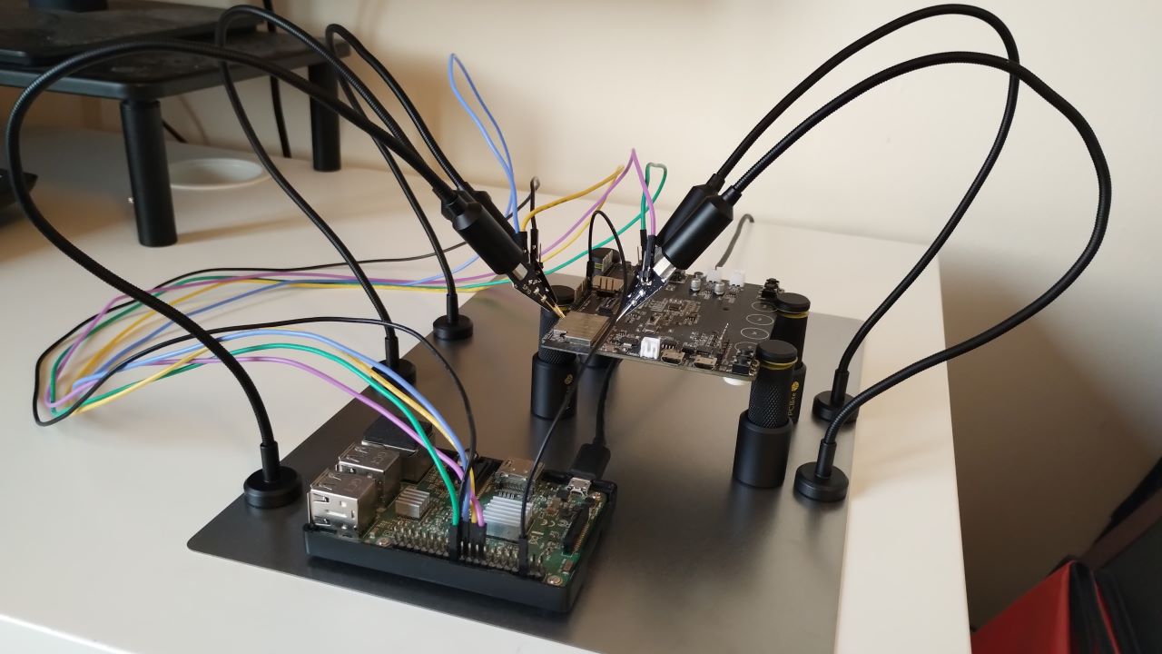
- RPI Pin 17 -> ESP32 Module Pin 17 (/HOLD/RESET need to be driven high)
- RPI Pin 24 -> ESP32 Module Pin 19 (SPI0 CE0)
- RPI Pin 23 -> ESP32 Module Pin 20 (SPI0 SCLK)
- RPI Pin 21 -> ESP32 Module Pin 21 (SPI0 MISO)
- RPI Pin 19 -> ESP32 Module Pin 22 (SPI0 MOSI)
I also connected a logic analyzer to all signals for debugging purposes.
Once connected, I can try to identify the flash chip, by typing the following command:
$ flashrom -VV -p linux_spi:dev=/dev/spidev0.0,spispeed=1000
[...]
SFDP parameter table header 0/1:
  ID 0x00, version 1.0
  Length 36 B, Parameter Table Pointer 0x000030
Parsing JEDEC flash parameter table...
  3-Byte only addressing.
  Status register is non-volatile and the standard does not allow vendors to tell us whether EWSR/WREN is needed for status register writes - assuming EWSR.
  Write chunk size is at least 64 B.
  Flash chip size is 4096 kB.
  Block eraser 0: 1024 x 4096 B with opcode 0x20
  Tried to add a duplicate block eraser: 1024 x 4096 B with opcode 0x20.
  Block eraser 1: 128 x 32768 B with opcode 0x52
  Block eraser 2: 64 x 65536 B with opcode 0xd8
done.
I can confirm on the logic analyzer, the SPI command to identify the chip and the response:
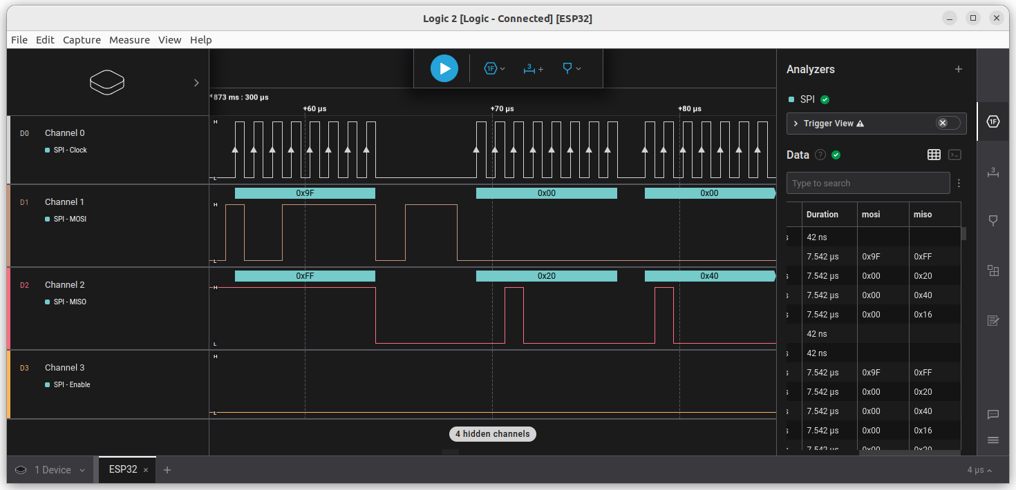
Now we can download the content of the flash:
 $ flashrom -p linux_spi:dev=/dev/spidev0.0,spispeed=1000 -r esp_flash.bin
 [...]
 Reading flash... done.

 $ ls -l esp_flash.bin
-rwx------+ 1 david david 4194304 Jan 14 17:28 esp_flash.bin
We now have the content of the flash. Extracting the different contents from the image, and reverse engineering the firmware will be covered be in future articles.
Issue fixed in recent modules
Looking at the more recent modules versions from Espressif, the internal SPI pins of the SoC are not connected anymore to the module pins. It is possible that Espressif identified this as a weakness and decided to make the firmware dump more complicated. As you can see, pin 17 to 20 are now not connected:
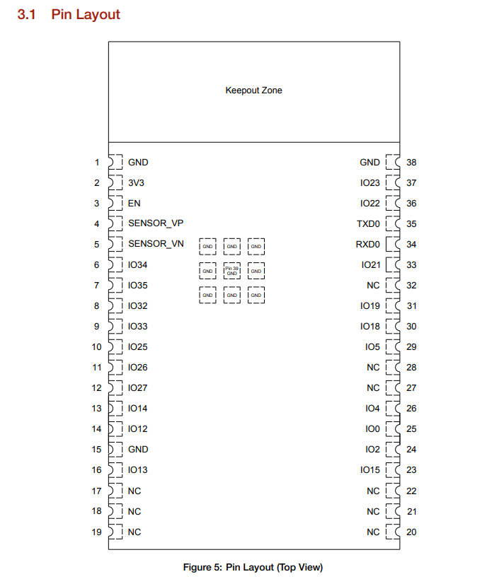

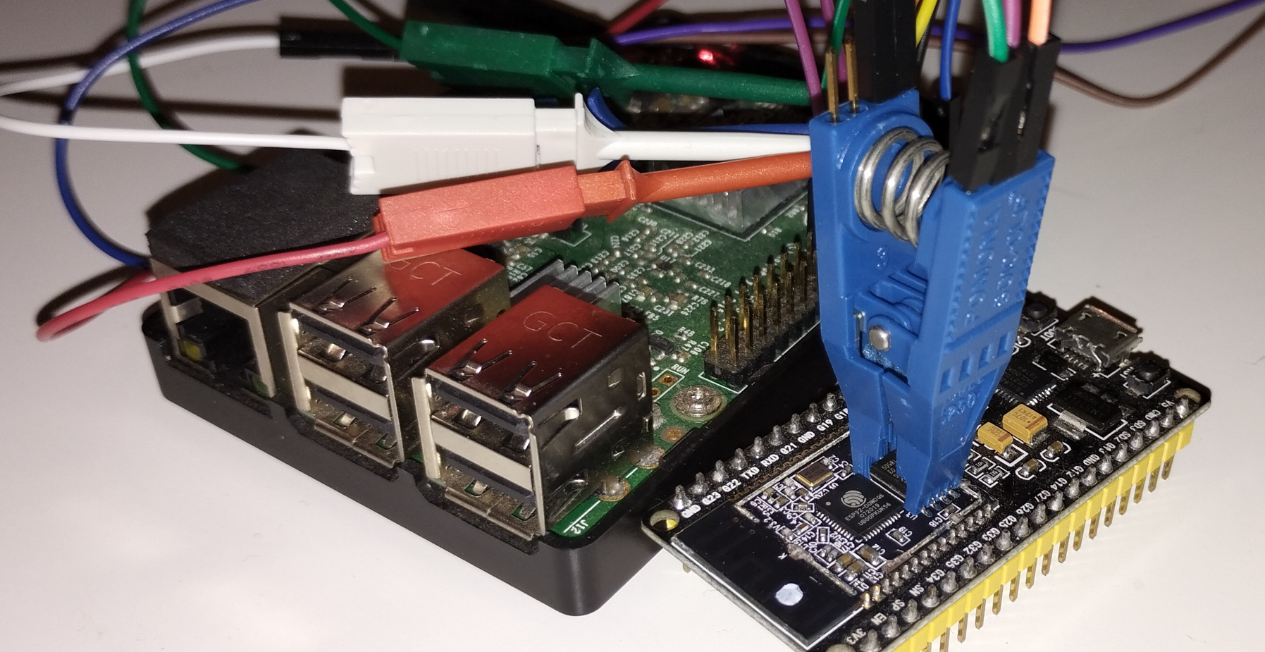
In such case, the metal shield needs to be unsoldered to so flash chip can be accessible, as I’ve done here with a SOIC-8 Test clip connected to the chip:
Summary
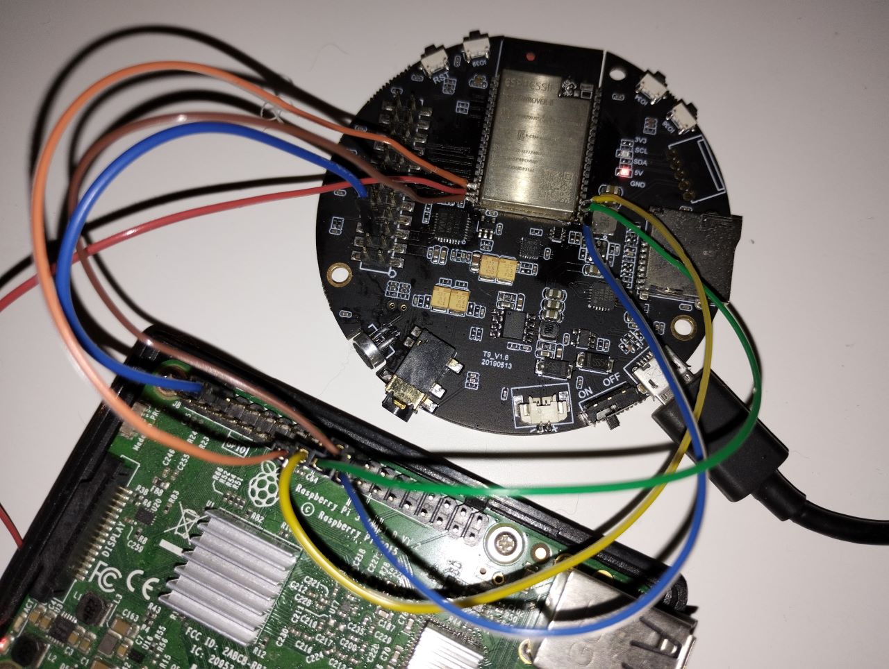
This article demonstrates that even if UART, JTAG, DFU are disabled, it is still possible to dump the content of the flash, which includes the firmware. For some versions of esp32 modules, this job is actually very easy because the internal SPI port is directly routed to external pins of the module. Here is another picture, where I directly soldered these pins:
Thank you for reading!
